55619 – PERISTALTIC PUMP SERVICE KIT
To suit Pool Lab ASP (Auto Sampling Photometer) and Pool Lab Hybrid Systems
for both acid and liquid chlorine feed peristaltic pumps. Replace every 12 months.
You can download a PDF of these instructions here,
or view an instructional video here
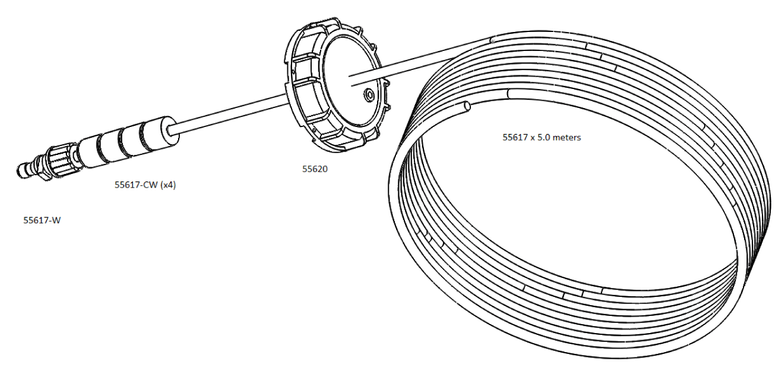
Kit Contains:
|
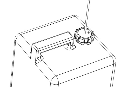
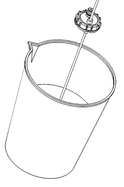
Drum Cap - Assembled with tubing and weights |
 |
| Pump Tube & Roller Kit | 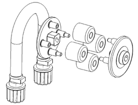 |
| Injector Valve | 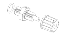 |
| 5g Silicone Lube |  |
READ THIS BEFORE SERVICING
- ALWAYS WEAR SAFETY GOGGLES AND GLOVES WHEN SERVICING THE PERISTALTIC PUMP AND/OR CHEMICAL FEED LINES
- USE A TYPE E RESPIRATOR TO PROTECT AIRWAYS FROM ACID FUMES
- USE OF ACID RESISTANT BOOTS IS RECOMMENDED
- IT IS ADVISED (WHERE POSSIBLE) TO FLUSH THE CHEMICAL LINES WITH FRESH WATER BEFORE SERVICING TO REDUCE THE CHANCE OF SPILLIAGE
- ALWAYS ENSURE THERE IS PLENTY OF FRESH WATER READILY AVAILABLE TO RINSE ANY SPILLED CHEMICALS, OR TOOLS / CLOTHING / SKIN / EYES ETC. EXPOSED TO CHEMICALS
- THE POOL LAB PERISTALTIC PUMP HAS BEEN DESIGNED FOR USE WITH 16.5% HYDROCHLORIC ACID ONLY. USE OF HIGHER STRENGTH HYDROCHLORIC ACID (OR OTHER ACID TYPES) MAY DAMAGE EQUIPMENT, AND RESULT IN A SAFETY HAZARD
WARNING: Extreme care must be taken when working with the acid feed tubing as under certain
conditions the tubing may be pressurized. Loosen the acid drum reservoir cap to relieve any potential
pressure on the inlet. If acid injection point is below water level, ensure appropriate isolation valves
are closed and vent isolated plumbing section to relieve any pressure before proceeding.

Hydrochloric (Muriatic) Acid Warnings
- ➔ Read warnings on the label. Do not allow acid to come in contact with skin, eyes or mouth, and follow directions on label if accidental contact occurs.
- ➔ Hydrochloric acid is highly corrosive, and will corrode metallic surfaces.
- ➔ General advice for accidental contact with Hydrochloric Acid is to flush with fresh cold water for at least 15 minutes, and remove any contaminated clothing. Seek immediate medical attention.
- ➔ Hydrochloric Acid does produce dangerous fumes. These fumes are highly irritant to skin, eyes and airways, and can also damage equipment. Always ensure the area is well ventilated when handling acid.
- ➔ Always wear protective clothing when handling acid or servicing the acid dosing system. Acid resistant gloves, eye protection or face shield, boots and a suitable respirator are recommended.
- Note: a Type E filter approved to EN141, European Standard for Gas Filters is suitable for Hydrochloric acid fumes.
- ➔ Service acid dosing pump at least every 12 months.
- ➔ When diluting acid, always add acid to water. Never add water to acid.
- ➔ Store acid in a cool, dry, and well ventilated place away from sources of moisture. Keep away from incompatible materials, such as oxidizing agents, organic materials, metals and alkalis.
Acid Dosing System Warnings
- ➔ For installations where an acid leak could result in damage to property such as flooring or nearby equipment, or where a leak may result in a safety hazard, the drum must be located within an additional containment vessel with a capacity no less than 200% of the acid drum volume. The containment vessel must be made from a plastic suitable for containment of hydrochloric acid eg. High Density Polyethylene (aka. HDPE) and should ideally be located directly below the acid pump and feed tubes so that it may catch any potential leaks from acid feed tubing and fittings. This will minimize the risk in the event of a leak.
- ➔ The area around the acid dosing system, including the storage drum and feed tubes must be inaccessible to children, animals and other unauthorised persons.
- ➔ The acid drum MUST NOT BE located in direct sunlight as heat will cause the drum to pressurize, resulting in a safety hazard and increased risk of leakage.
- ➔ Where a SPA ONLY system exist, acid drum volume must be limited to 5 Litres.
- ➔ The acid drum and acid dosing system components must be located in a well ventilated area (preferably a shaded outdoor area) where there is minimal risk of damage to persons and/or property in the event of an acid leak.
- ➔ For indoor installations the installer must complete a risk assessment and discuss plans with the property owner for minimizing risks to persons and property.
- ➔ All elements of the acid dosing system must be regularly inspected to ensure it is in safe working order. Component must be replaced as per the instructions if degradation is evident.
Poolpower Australia Pty. Ltd. will not be liable for damage where a duty of care has not been demonstrated with respect to the installation of this equipment or its ongoing maintenance.
Peristaltic Pump Service Procedure
Step 1: Flush the feed pump and tubing with fresh water.
The filtration system must be running to perform this task. Change filtration mode to ON if required, and use the ACID PRIME or LCHL PRIME function in the ASP TOOLS menu to flush water through the tubing.
- a) Loosen the fume stop cap to relieve any pressure in the drum
- b) Remove the drum cap, and place end of feed line into a bucket of fresh water
- c) On the chlorinator control panel, press and hold VIEW until the MAIN MENU appears
- d) Navigate to ASP TOOLS and press VIEW (ASP TOOLS menu appears)
- e) Navigate to ACID/LCHL PRIME and press VIEW
- f) Press VIEW to start the feed pump (60 second timer)
- g) Allow PRIME to finish, and repeat
- h) Press BACK button at least 3 times to return to the HOME VIEW
Note: This procedure is never guaranteed to flush all chemicals from the system, especially if the pump has not been performing well. Always wear appropriate protective clothing and proceed with caution when handling liquid chlorine and/or acid while servicing the dosing system.
Step 2: Prepare the system for servicing.
Turn OFF and disconnect the filtration pump. Relieve the plumbing of any pressure or vacuum.
- a) Change the FILTRATION MODE to OFF using the MODE button
- b) Disconnect the filtration pump power cord to prevent accidental start up
- c) If the acid injection point is below water, close both suction and return isolation valves
- d) Relieve any pressure or vacuum from the plumbing section that has the injection point, and drain enough water from the plumbing system so that the injection point is above the water level*
* The procedure for (d) depends on your system components and configuration
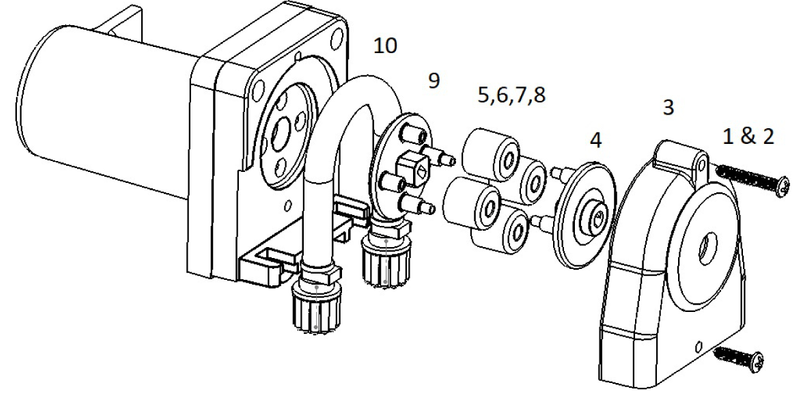
Step 3: Remove the old squeeze tube and rollers.
- a) Loosen and remove both lock nuts securing feed tubing to the pump, and disconnect both feed tubes
- b) Remove 2x screws (1, 2) securing the clear plastic outer cover (3), and remove cover
- c) Remove old squeeze tube (10) and discard
- d) Remove outer rotor half (4) and discard
- e) Remove 4 x rollers (5,6,7,8) and discard
- f) Remove inner rotor half (9) - this may require a flat head screw driver or similar as a lever
Step 4: Use a cloth to wipe clean the pump housing and cover to remove all the old grease.
Step 5: Install and lubricate new squeeze tube and roller parts.
.
- Lubricate the backing plate where it contacts the inner rotor half
- b) Install the inner rotor half (inner and outer rotor halves are identical parts)
- c) Add a small amount of lubricant to the inside running edge of each roller (ie. the hole)
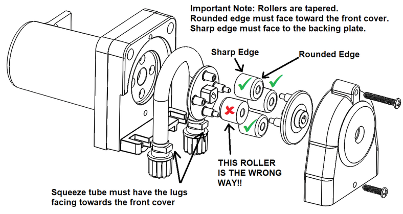
- d) Install 4 x rollers. Ensure all 4 have the rounded edge facing outwards
- e) Install the outer rotor half, and add a small amount of lubricant to the outer face
- f) Lubricate rollers and squeeze lube liberally with silicone lubricant
- g) Install the squeeze tube - ensure tube connectors have the square lugs facing outwards
- h) Replace cover - position top edge in place first, then apply downward and inward force
- i) Replace 2 x screws to secure cover
When looking at the front of the pump, the inlet is on the left and the outlet is on the right. Tighten lock nuts by hand only.
Step 6: Replace injector.
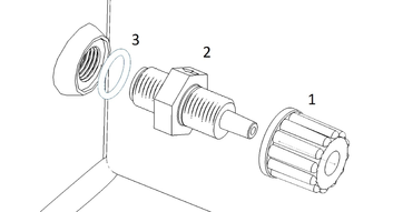
- a) Loosen and remove lock nut (1) securing tubing to injector, and disconnect tube
- b) Loosen and remove injector (2) - this may require a spanner if too tight
- c) Fit new injector, ensuring o-ring (3) is in place and tighten by hand only
Step 7: Replace feed tubing.
- a) Cut 2x lengths of new feed tubing as required:
- 1 x for pump to injector connection
- 1 x for pump to reservoir connection
- b) Connect tubing from pump outlet to injector, and tighten lock nuts by hand only
- While tightening the injector lock nut, hold the injector body in place with a spanner to prevent over-tightening the cell housing thread
- c) Connect tubing to pump inlet and tighten lock nut
Step 8: Prepare the system for operation.
- a) Check all pipe unions are tight
- b) Check both suction and return valves are open and positioned correctly
- c) Ensure the filtration mode is set to OFF, and reconnect filter pump power lead to the pump outlet socket
Step 9: Start the system, and check for leaks.
- a) Change filtration mode to ON using the MODE button
- b) Ensure water is flowing normally, and pressure gauges reading normal
- c) Check plumbing, feed tubing and connectors for any signs of leaks
Step 10: Test pump operation with water, using the prime function.
- a) Place the inlet end of the acid feed tube in a bucket of fresh water
- b) On the chlorinator control panel, press and hold VIEW until the MAIN MENU appears
- c) Navigate to ASP TOOLS and press VIEW (ASP TOOLS menu appears)
- d) Navigate to ACID/LCHL PRIME and press VIEW
- e) Press VIEW to start the feed pump (60 second count down timer begins)
- f) Observe water being pumped along the feed tubes
Step 11: Fit fume stop cap back onto reservoir.
Ensure the end of the feed tube can reach the bottom of the drum and adjust length if required.